Photoelectric Optic Wireless Timing Gates
In sprinting accurate timing systems are an important factor for evaluating your performance. In top speed training this requires accuracy up to 0.001s at the most closest of finishes. In training athletes use such systems to accurately measure their sprinting performance and speed to improve their training quality.
Alternative systems are available for purchase, but they are often between 400 to a 1000 euros. This was not in my track and fields team's budget. Therefore, I set out to create my own alternative timing system. The system consists of 2 modules, a starting module and a finish module. More of these modules can be added in between to potentially calculate more split times, but this documentation focuses only on the start and finish module.
All files can be found and downloaded from this GitHub repository.
Principles and working prototype.
The base of the system is using a Photoelectric through-beam production line sensor from SICK. I acquired this sensor second hand for cheap. This option allowed for accurate tracking upto a frequency of a 1000hz. This also meant that I did not have to create my own photo electrc through-beam sensor, which could prove to be inaccurate. Any through-beam laser sensor can work for this project.
The list of hardware requirements for this projects are as follows:
- 2x Arduino Nano
- 2x SICK Photoeletric through-beam sensor or own DIY alternative
- 2x 1602 LCD screens
- 12 volt battery pack or alternatively 6x 18650 batteries
- 2x nrf24lo1 and power board modules
- 2x 9 volt batteries
- 2x 10 uF capacitors
- 4x Any Camera tripod
- Some sort of housing/case
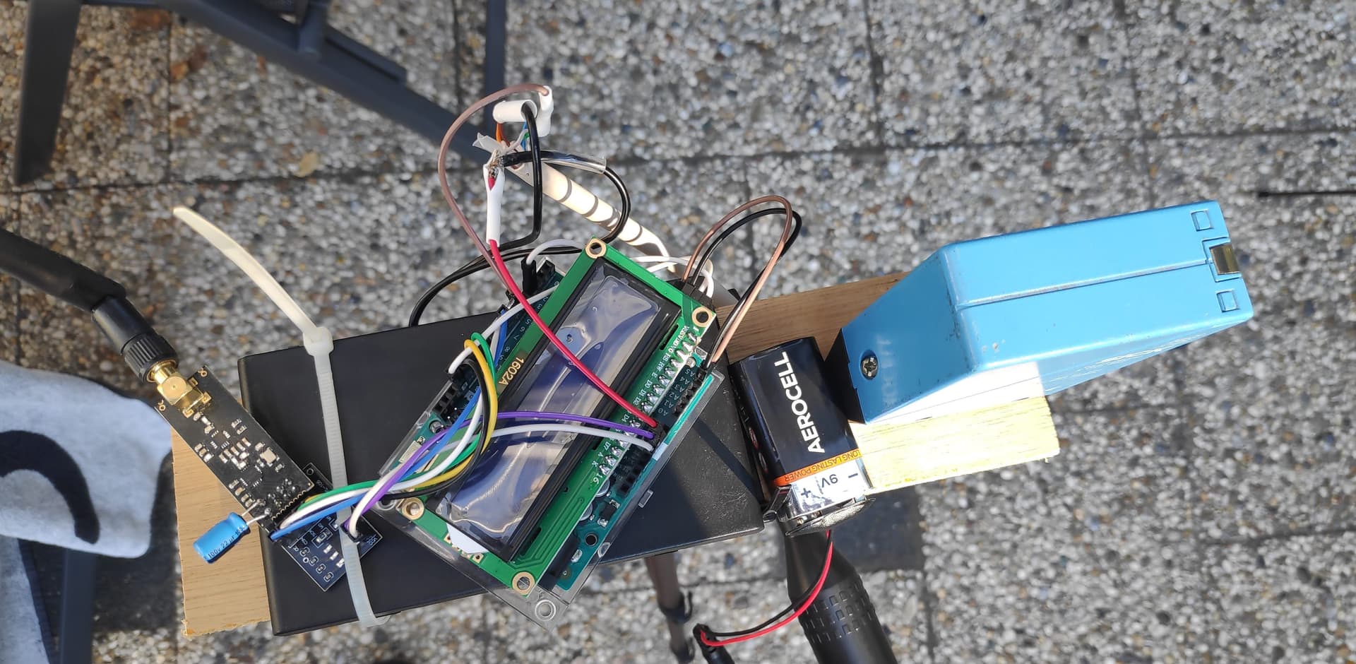
I started with a very crude prototype to test the concept of the system, and to verify the connectivity between the two modules. This resulted in a version on a quick scrap piece of wood, where I quickly soldered all the parts together. This version was also tested on the track to test the range of the system. Theoretically the system is rated up to 1000 meters of range, but this proved to be inconsistent based on multiple forums. The tests on track showcased latency below 3 micro seconds.
Creating a custom PCB for the project
After the initial concept was proven to be functional, I started working on a PCB for the project. Due to the SICK sensor requiring 12V and the arduino requiring 5v the power tree required converting. The goal of the project was to create a slim and effective alternative to the commercial products. Therefore, the battery had to be compact aswell. This resulted in a 3.7v LIPO battery, due to the dimensions. This however created the requirement of 2 boost conversions to be present on the board.
I started working on the PCB schematics in KICAD, I used two buck-boost converter schematics that I had already used in a different project. I know this is overkill, and these parts are also expensive. In a later version I will simplify the project to work on a single more suitable boost converter. This resulted in the following schematics:


Some notable parts of the schematic are the power improvements and also the stabalization of the power tree to the NRF24lo1 module. In the concept version the NRF module was very picky with power fluctuations, resulting in inconsistent performance. Therefore, I recreated the power adapter board into the PCB, and changed the cheap adapter boards LDO to an improved version. Also, a 10uF capacitor was added to the power line to stabalize any sudden power drops. In order to remove any last power fluctuations a small ferrite bead was added to the power line aswell.
As can be seen in the schematic a fuse and TVS was added to increase power tree safety. This is mainly due to the usage of LIPO batteries, which can be dangerous when short circuited.
After the schematics were finished, I started working on the PCB layout. The goal was to create a small and compact PCB that could fit inside a small case. After multiple iterations I came to the following design:

M2 Mounting holes were added for manufacturability and fixation. Once I had these finished, I ordered my PCB from PCBway.com, whom were kind enough to sponsor this project. After a very easy and intuitive experience I received my PCB's after around 1.5 weeks. The PCBs turned out great and were fully functional. If you are interested in performing this project aswell, I would highly recommend ordering from them aswell.
After soldering in the main parts, the resulting PCBs can be seen below:


I chose to attach the NRF module at the back side of the PCB for better protection and to reduce interference from other components, but also to remove any wiring. This also had favorable impact on the compact design. The arduino is installed on female headers to be replaceable. However, if a compact design is the main goal the arduino can also be soldered directly into the PCB saving around 1 cm of width.
Final Assembly and Usage
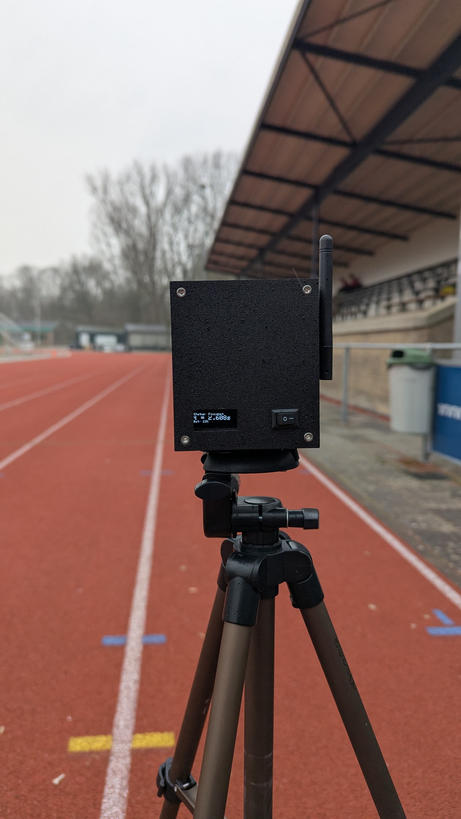
After the PCBs were assembled, I moved on to assembly. I created a 3D-printed case to house all the components and attached a mounting hole that is universal for tripodmounts. This created a quick attachable solution for mounting the modules on tripods. The final assembly can be seen below: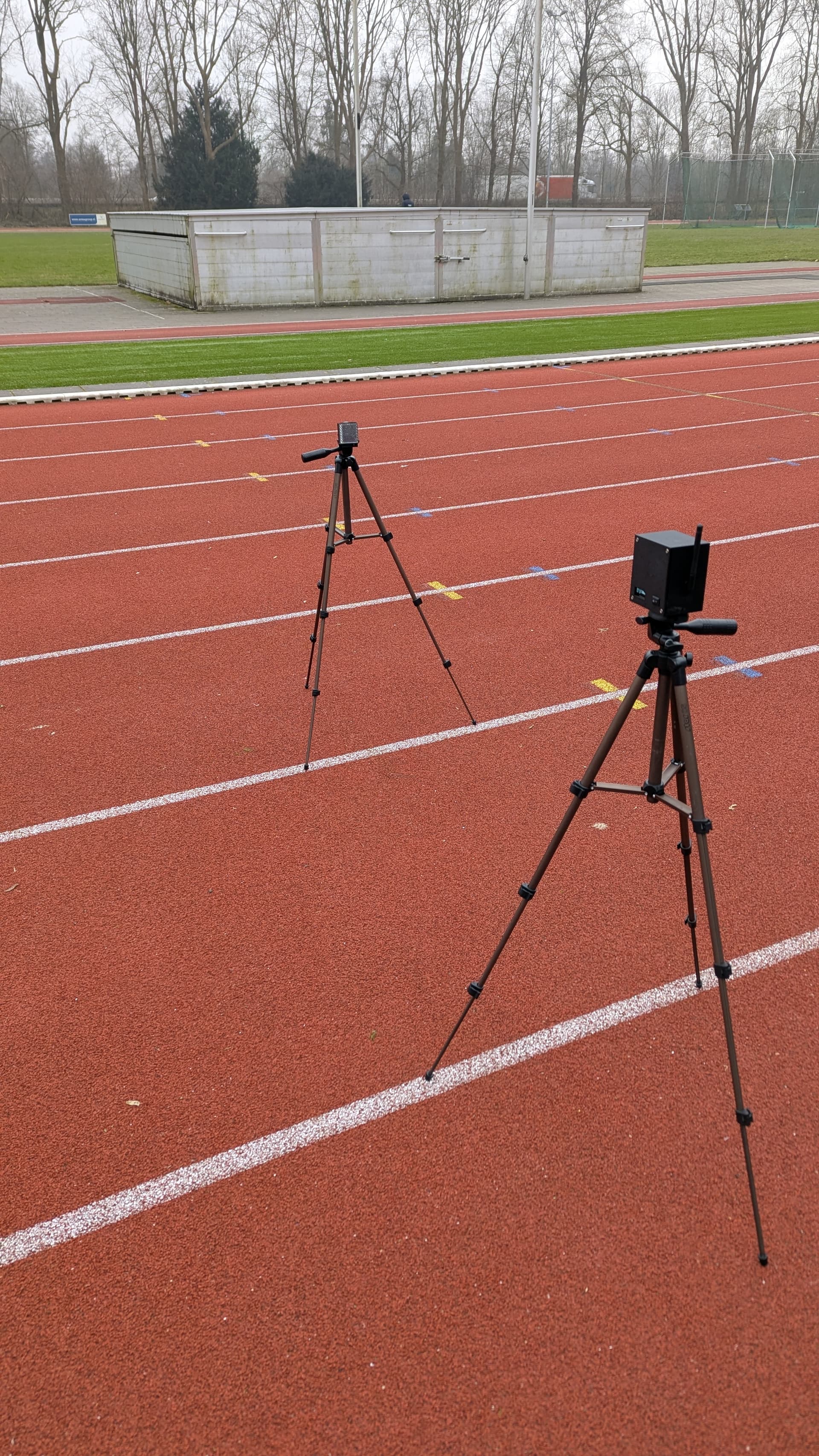
The final Bill of Material can be seen in the picture below:
The project consists of:- 2x Arduino Nano
- 2x SICK Photoeletric through-beam sensor or own DIY alternative + reflector
- 2x OLED 0.91" screen
- 3.7 slim LIPO battery pack
- 2x nrf24lo1+PLA
- 4x Any Camera tripod
- Some sort of housing/case
- Some JST connectors to connect the batteries and other components
I used some hard to get components, and will be updating this version to be more accessible in the future. I will also be testing the final latency on track with some distance in between the sensors to verify my assumptions and calculations.
If anybody is interested in this project or wants to know more, feel free to contact me.